Triangular oscillator - Operational amplifier slew rate - IV part
The fourth article in series
about triangular oscillator is intended to explain operational amplifier slew
rate parameter since it is important parameter when you are dealing with signal
generators like it is square wave signal generator. Op amps are not ideal as
any other components, and it is important to know how to choose right
operational amplifier for signal generator applications.
Slew rate
Operational amplifiers are
not ideal components as any other electronic components and/or devices, there
are a lot of different op amps designed with different slew rate value as it is
presented on Figure #1. Slew rate is the parameter which determines how fast operational amplifier is able to change output signal/voltage regarding input voltage changes. The higher the slew rate value means faster operational amplifier and vice versa. Internally, operational amplifier slew rate parameter depends on the compensation capacitance Cc, very small amount of integrated capacitance (here you can ask yourself the question: why bypass capacitors are not integrated in the chip?), in order to prevent op amp output signal instability (signal oscillations in time when signal is changed from the high to the low voltage value and vice versa). To present how slew rate acts on square wave signal
generation three different measurements were done, with LM224, LM324 and TL074
operational amplifiers.
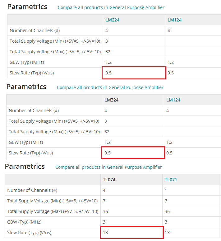 |
| Figure #1: Slew rate parameter for: LM224, LM324 and TL074 Texas Instruments |
Slew rate equation
In the second article frequency
equation has been introduced and it depends on several resistors and
capacitance. But that is not guarantee that calculated frequency will be
generated at the operational amplifier output since it was presented as ideal component until this fourth article. To be
sure that desired frequency will be generated, it is important to choose op amp
with adequate slew rate. In order to choose op amp it is important to do
calculations presented at Figure #2.
| Figure #2. Slew rate equation, depends on frequency (f) and peak voltage (V) |
For example: for the 18000
Hz frequency (18KHz) and peak voltage 12VDC, calculated slew rate is 1.357344
V/uS. That means that operational amplifier with the slew rate equal or greater
then 1.357344 V/uS must be chosen in order for the square wave signal to be
generated with right shape and desired frequency. If we chose op amp with
smaller slew rate square wave signal will be deformed, and we will see that from the
following video clips.
Since for the 18KHz slew rate is 1.357344 V/uS, we will chose the op amp TL074 since it has slew rate 13V/uS. With TL074 we can expect that square wave signal will be generated with right shape, desired frequency of 18KHz and peak voltage of the 12VDC.
Slew rate video clips
Since for the 18KHz slew rate is 1.357344 V/uS, we will chose the op amp TL074 since it has slew rate 13V/uS. With TL074 we can expect that square wave signal will be generated with right shape, desired frequency of 18KHz and peak voltage of the 12VDC.
Slew rate video clips
Video#1: VF Driver - Slew rate related to the TL074 Texas Instruments
operational amplifier. Generated signal has a pure square wave shape
since TL074 is the high speed op amp, slew rate is 13V/uS, much larger in comparison with the calculated slew rate value of 1.357344 V/uS. That is the reason why generated square wave signal has pure shape with voltage peak of desired 12VDC. The VF driver power
supply is 12VDC. Target frequency is 18KHz (square wave).
Video#2: VF Driver - Slew rate related to the LM324 Texas Instruments operational amplifier. The generated signal doesn't have a pure square wave shape, it is more triangular signal since LM324 OpAmp is not the high speed op amp, slew rate is 0.5V/uS, much less in comparison with the calculated slew rate value of 1.357344 V/uS. That is the reason why generated square wave signal is deformed and looks much like a triangular signal - operational amplifier doesn't have ability to change signal at output stage at desired frequency of 18KHz with 0.5 V/uS slew rate value. The VF driver power supply is 12VDC. Target frequency is 18KHz (square wave).
Video#3: VF Driver - Slew rate related to the LM224 Texas Instruments operational amplifier. The generated signal doesn't have a pure square wave shape, it is more triangular signal since LM224 op amp is not the high speed op amp, slew rate is 0.5V/uS, much less in comparison with the calculated slew rate value of 1.357344 V/uS. That is the reason why generated square wave signal is deformed and looks like a triangular signal. In comparison with the LM324 op amp which has the same slew rate value, LM224 is not able to generate target frequency of 18KHz as it is presented on the video clip. The VF driver power supply is 12VDC. Target frequency is 18KHz (square wave) but only 16.5KHz was generated (but anyway, it is not square wave signal).
 |
Operational amplifiers |
Related articles:
Triangular oscillator - Fundamentals - I part
Triangular oscillator - Frequency - II part
Triangular oscillator - PWM square wave signal - III part
SERPENT I - DC motor controller
SERPENT I - PCB DIY (do it yourself) assembling - video clips examples
SERPENT II - Pit VIPER Rattle - DC motor controller/driver
How to design LM324 Astable Multivibrator
How to build do it yourself printed circuit board (DIY PCB) by using thermal transfer method
Programmable autonomous vehicles – Fundamentals, Part I
Power switch as current amplifier
How to design voltage reference by limiting current consumption
Fake VC830L digital multimeter
Low pass filter and voltage stabilization
zilsel-invent assumes no responsibility or liability for any errors or inaccuracies that may appear in the present document. Specification and information contained in the present schematics are subject to change at any time without notice.


For ece important points & formulas CLICK HERE
ReplyDelete