Triangular oscillator - PWM square wave signal - III part
This article is dedicated to the second modulation related
to the VF driver revision 1.0. Pulse width modulation (short PWM) is the method
of the signal pulse width changes in order to control rotation speed of the DC
motor shaft. This article will explain measurements taken by the oscilloscope,
frequencemetre and voltmeter in order to present PWM signal modulation.
VF driver revision 1.0 measurements
This part will explain video clip related to the VF driver
revision 1.0 measurements taken by the oscilloscope, frequencemeter and
voltmeter in order to present pulse width signal modulation. This video is
split into the two parts: the first part is related to the frequency modulation
and the second is related to the PWM signal modulation.
Video: VF driver revision 1.0 measurements
Frequency measurements
Frequency is already explained under the previous article
(II part), in this example the frequency is changed by changing variable
resistor resistance (variable resistor is implemented with potentiometer
configured as a variable resistor, for details take a look under VF driver revision 1.0 specification). As you can see from the first 1 minute and 30
seconds of the video clip, by changing the resistance of the R2 resistor
frequency are changed accordingly. The signal is presented by the oscilloscope
and frequencemetre (left digital multimeter), greater frequency is presented
with more pulses on the oscilloscope screen, while smaller frequency is presented
with less pulses on the oscilloscope screen, at the same time frequencemetre
show generated frequency (Figure #1).
 |
| Figure #1: Frequency measurement - VF driver revision 1.0 |
We already have had a discussion about the frequency, it is
the signal modulation which allows us to find the right frequency of the chosen
DC motor. When right frequency has been found, it is not possible to change it
anymore. If we do need speed control related to the DC motor shaft, second
modulation must be implemented, which lead electrical schematic changes from
the previous article by adding additional comparator (without hysteresis). This
comparator is presented on the Figure #2 and it is consisted of the operational
amplifier (3) and potentiometer P2 related to voltage reference changes. Noninverting
input of the operational amplifier (3) is connected to the triangular signal of
the free-running triangular oscillator circuit, while inverting input of the
operational amplifier (3) is connected to the voltage reference point generated
by the potentiometer P2.
 |
| Figure #2: Square wave generator with pulse width modulation - comparator without hysteresis (operational amplifier (3)) |
How PWM square wave signal generator work?
The Figure #3 presents how PWM square wave signal generator
work. There are four cases.
 | ||
| Figure #3: PWM signal in comparison to the triangular signal and the Vref point |
First case (Figure #3.a): The voltage reference Vref (signal marked with point 3) is generated by the potentiometer P2 (Figure #2), triangular signal is connected to the noninverting high impedance input of the operational amplifier (3). When triangular signal becomes greater than the Vref voltage reference, the output of the operational amplifier (3) goes from the low signal level (~0 volts) to the ~Vcc voltage (depends on chosen operational amplifier – rail-to-rail operational amplifier = Vcc). When triangular signal becomes lower than the Vref voltage reference, the output of the operational amplifier (3) goes from the high signal (~Vcc) to the low signal lever (~0). The width of the signal is determined by the Vref point value on the Y axis on the diagrams
Second case (Figure #3.b): it is the same explanation as in
the first case, but in this case Vref point is greater in comparison to the
first case. What does that mean? That means that the pulse width will be
smaller in a second case in comparison to the first case, as it is presented
on the Figure #3.b. Now it is clear, if we do change the value of the Vref
voltage point reference, different width of the signal pulse will be generated.
The pulse width of the signal is directly reflected to the voltage value used
to drive DC motors.
Third case (Figure #3.c): it is the same explanation as in
the first case, except that in this case the Vref point reference is set above
the highest triangular signal point. That means that the PWM square wave signal
is not generated and it is zero voltage at the operation amplifier (3) output.
In this case the DC motor shaft is stopped.
Fourth case (Figure #3.d): it is the same explanation as in
the first case, except that in this case the Vref point reference is set below
the lowest potential point of the triangular signal. That means that triangular
signal is always greater than Vref which lead to the ~Vcc output of the operational
amplifier (3). In this case pulse of the signal does not exist and DC motor is
driven by the maximum power supply voltage.
PWM measurements
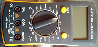
PWM measurements are based on voltage measurements taken by
the digital multimeter VC830L. As we can see starting from the 1 minute and 30
seconds (video clip), by changing Vref point reference with the potentiometer P2 the width
of the signal pulse are changed accordingly. When the signal width gets wider
the more voltage value is measured by the VC830L digital multimeter and vice
versa. Three different measured voltages are presented in Figure #4, and as you
can see, for small pulse width smaller voltage value is generated, and vice
versa.
 |
| Figure #4: PWM signal measurements |
This generated voltage value is directly
reflected on the speed of the DC motor shaft - higher the generated PWM voltage -> faster DC motor shaft rotation, and vice versa. That doesn’t mean that
square wave signal with pulse width modulation is directly used to drive DC
motors since VF driver does not have appropriate power to run it. Instead, VF
driver is used to drive a DC motor by providing control signal pulses to the DC
motor controller/driver (like it is SERPENT I or SERPENT II), with responsibility to provide enough current amplification
to driver DC motors.
Related articles:
Triangular oscillator - Fundamentals - I part
Triangular oscillator - Frequency - II part
Triangluar oscillator - Operational amplifier slew rate - IV part
SERPENT I - DC motor controller
SERPENT I - PCB DIY (do it yourself) assembling - video clips examples
SERPENT II - Pit VIPER Rattle - DC motor controller/driver
How to design LM324 Astable Multivibrator
How to build do it yourself printed circuit board (DIY PCB) by using thermal transfer method
Programmable autonomous vehicles – Fundamentals, Part I
Power switch as current amplifier
How to design voltage reference by limiting current consumption
Fake VC830L digital multimeter
Low pass filter and voltage stabilization
zilsel-invent assumes no responsibility or liability for any errors or inaccuracies that may appear in the present document. Specification and information contained in the present schematics are subject to change at any time without notice.


Comments
Post a Comment