SERPENT II Pit VIPER - PCB DIY (do it yourself) assembling - video clips examples
This is an initial version of the blog post about how to do assembling / soldering of the SERPENT II Pit VIPER DC motor controller/driver. In time this blog post will be modified with additional material like screenshots, explanations, additional examples etc. Currently this blog post provides only video clips related to the soldering process of the DC motor controller. Note: all zilsel-invent video clips are real, without additional video editing
and it was taken by Logitech HD720p web camera. Also, you will never
hear a fancy mumbo jumbo speaker (announcer), since zilsel-invent is
intended for the >makers community< and it will always be like
this.
Step #1: SERPENT 2 - Viper, IRF3710 Power MOSFET assembling / soldering.
Step #2: SERPENT 2 - Viper, rectifier diodes assembling / soldering.
Step #3: SERPENT 2 - Viper, male pin header connectors assembling / soldering.
Step #4: SERPENT 2 - Viper, blue signal LEDs assembling / soldering.
Step #5: SERPENT 2 - Viper, blue screw connectors assembling / soldering. These connectors are used to connect DC motors.
Step #6: SERPENT 2 - Viper, bypass capacitors assembling / soldering.
Step #7: SERPENT 2 - Viper, 2K2 resistors assembling / soldering.
Step #8: SERPENT 2 - Viper, voltage regulator 7815 assembling / soldering.
Step #9: SERPENT 2 - Viper, socket DIP 6 and DIP 8 assembling / soldering. DIP 6 related to opto-couplers, DIP 8 related to the LM393 comparator as gate POWER MOSFET driver.
Step #10: SERPENT 2 - Viper, white screw connectors assembling / soldering. These connectors are intended for microcontroller unit like Arduino. Screw connector related to the power supply has been assembled as well.
Step #11: SERPENT 2 - Viper, electrolytic capacitors assembling / soldering.
Step #12: SERPENT 2 - Viper, first test of the white-black assembled edition.
Step #13: SERPENT 2 - Viper, overview of the white-black assembled edition.
zilsel-invent assumes no responsibility or liability for any errors or inaccuracies that may appear in the present document.
Specification and information contained in the present schematics are subject to change at any time without notice.
Step #13: SERPENT 2 - Viper, overview of the white-black assembled edition.
Related articles:
SERPENT II - DC motor controller
How to design LM324 Astable Multivibrator
How to build do it yourself printed circuit board (DIY PCB) by using thermal transfer method
Programmable autonomous vehicles – Fundamentals, Part I
Power switch as current amplifier
How to design voltage reference by limiting current consumption
DC motor torque vs DC motor speed
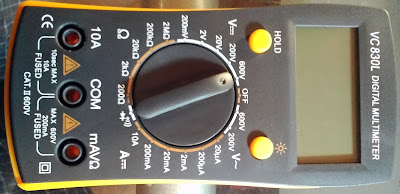
Fake VC830L digital multimeter
Low pass filter and voltage stabilization
How to design LM324 Astable Multivibrator
How to build do it yourself printed circuit board (DIY PCB) by using thermal transfer method
Programmable autonomous vehicles – Fundamentals, Part I
Power switch as current amplifier
How to design voltage reference by limiting current consumption
DC motor torque vs DC motor speed
Fake VC830L digital multimeter
Low pass filter and voltage stabilization
zilsel-invent assumes no responsibility or liability for any errors or inaccuracies that may appear in the present document.
Specification and information contained in the present schematics are subject to change at any time without notice.


Comments
Post a Comment